4D BRIDGE SERIES - Features
Bridge Path Coordinate Systems
Bridge path coordinate systems (BCS) provide a unique way to simplify the modeling of curved bridges. A BCS is a warped rectangular coordinate system whose axes are station, elevation, and transverse offset. The station axis follows the curved geometry of the bridge centerline, and automatic transformations convert BCS geometry to Cartesian coordinates
How it Works
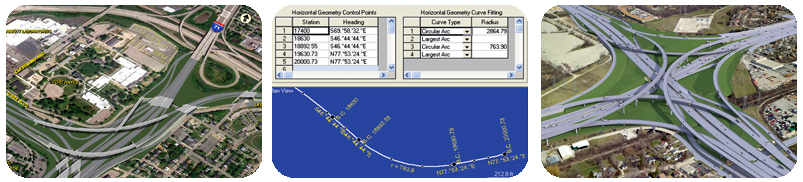
The horizontal geometry of the BCS is defined with stations and headings which can often be read off of design documents. BCSs allow the user to work in very simple coordinates despite any curvature of the structure by warping the usual x-axis into a curve that follows the curved center line of the bridge.
The warped "station (x) axis" is defined in two planes. Elevation and super elevation can be specified in addition to headings. Multiple bridge paths in the same project can be used to define girders, spiral on-and-off-ramps, and ground-level footings. These coordinate systems can also be used to specify joint coordinates and directions of supports, including for bearings and springs, and for the reporting of forces and other results.
LARSA, Inc. develops advanced software for the analysis and design of bridges and structures based on the finite element method.
LARSA is privately owned and based in New York, with all its software development and product support conducted in-house.
LARSA 4D Resources
- Download Current Version LARSA 4D Version 2026.R2 - July 17, 2026
- Sign into your LARSA 4D Web Account View licensing information and training materials
- Academic & Evaluation Licensing Request a hands-on LARSA 4D License
LARSA 4D Products
Contact
68 South Service Road, Suite 100
Melville, New York 11747
Phone: (800) LARSA-01
Phone: +1 212-736-4326
Fax: 631-454-5252
Email: info@larsa4d.com
© 2025 LARSA, Inc. All Rights Reserved.